The New Diamond DA50 Line

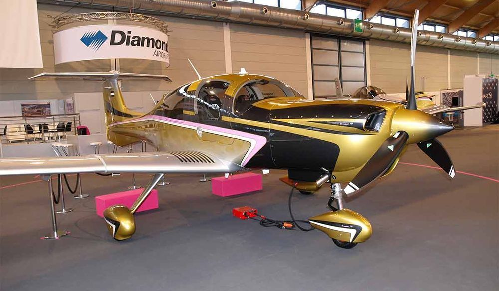
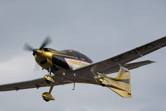
Diamond has joined the high performance single engine fray with the announcement of it’s new line of DA50 models.  Cirrus currently has the cornered the market on easy flying, fixed gear, speedy HP single engine airplanes.  But, (assuming that the Diamond DA50 gets certified in a timely manner and the appeal of the Jet A sipping SMA diesel engines appeals to a broad enough audience), Cirrus could have some competition soon.

The proposed Diamond DA50 will come in 3 different configurations, the IV, the V, and the VII.  The IV and the V will each burn under 10 GPH of Jet A. The VII will burn about 14 GPH of Jet A, using the same amount of fuel as a normally aspirated SR22, but at cheaper Jet A prices (plus the discount of fuel companies like CAA or AEG Fuels).

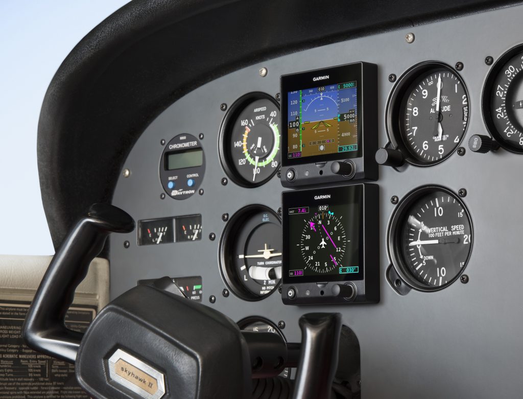
According to AOPA, all 3 Diamond DA50 models will be equipped with the Garmin G1000 NXi panel and the GFC 700 Autopilot. The Diamond DA50 -V will be the first model expected out next year, with the IV to follow soon after.  The wait for the VII will be a bit longer.

In testing, the Diamond DA50 -V showed true airspeeds of 173 knots with an expected range of almost 1100 miles.  Gone is the bubble canopy that greatly increased the green house affect of the airplane.  It’s replaced by two suicide doors, similar to what is on the Cessna TTx.  The single back seat door on the pilot’s side remains.

Carrying capacity will be greater than the Cirrus as well.  The Diamond DA50 -V will have a gross weight of around 4,000 pounds, giving it a useful load of 1,250 pounds, giving pilots a lot more flexibility in weight carrying.  The Diamond DA50 exterior will be fully customizable as well as advances in carbon fiber paint and decals has come a long way since the early 2000s when white was the only option.

Here are some basic specs for each DA50 model:

Diamond DA50 -IV

  • 230 HP
  • 4 seats
  • Less than 10GPH fuel burn

Diamond DA50 -V

  • 260 HP
  • 5 seats
  • 10 GPH Fuel Burn

Diamond DA50 -VII

  • 360 HP
  • 7 seats
  • Retractable Gear
  • Turboprop option

I am most excited to see the performance numbers on the VII model when it comes to market.  With a 360 HP engine and retractable gear, it seems like it will be a screamer.

There are also rumors that Diamond is working on a rotorcraft, the Dart 280, but there isn’t a flying model at the moment.

Similar Posts

  • Synthetic Vision Technology

    Let’s say you’re flying in the mountains of Colorado on a cloudy day.  There’s a solid layer from the surface all the way up to 14,000 feet.  You’re inbound to Eagle (KEGE) on the RNAV (GPS) D approach.  There are mountains next to you and below you, but you aren’t concerned since you can see them all.  The base of the last reported overcast layer was 3,000 feet, so you know you’ll break out before the MDA and land no problem.

    At 11,100 over AWACC, you clearly see the top of the mountain below you.  You are comfortably above it. You already have the runway in sight as well.  You pop out of the clouds on the approach at 9,700 feet, spot the airport and follow the tower’s instructions to circle north of the runway for a left base for runway 7.

    How could you see the mountains inside the clouds?  You have Synthetic Vision installed on your glass panel, that’s how.

    Aspen Synthetic Vision
    Aspen Synthetic Vision

    Synthetic Vision, which has actually been around since the ’70s when NASA and the US Military first developed it, was first FAA certified for the Gulfstream PlaneView flight deck in 2009.  Garmin, Avidyne, and Aspen are the main general aviation manufacturers of synthetic vision these days.  All Garmin PFDs are now equipped with Synthetic Vision while Aspen gives you the option to upgrade to Synthetic Vision when you get one of their PFDs installed.  Avidyne gives you Synthetic Vision in their R9 upgrade for the Cirrus.

    What is Synthetic Vision?  Basically, it’s a 3-D picture on the primary flight display showing terrain, obstacles, traffic, and runways.  It greatly enhances situation awareness in areas of terrain or high obstacles during IFR conditions or at night.

    The goal behind the development of Synthetic Vision was to decrease the amount of controlled flight into terrain (CFIT) accidents.  A CFIT accident consists of a perfectly airworthy airplane flown by a pilot (or autopilot) unintentionally into terrain. These accidents can happen in low visibility conditions or at night, but the reason is mainly due to the pilot losing track of his position in relation to obstacles or terrain (or water as was the case with JFK Jr.).

    With Synthetic Vision, the goal is to enhance pilot knowledge of what is around the airplane at all times. When you’re at altitude, the terrain below you looks flat.  When you start descending down amongst the rocks, the hills or mountains start to rise up on your screen.  For those used to the coloration with the 2-D terrain feature on a GPS unit, it translates very easily to the terrain coloration on a Synthetic Vision equipped PFD. Terrain that is between 100 and 500 feet below the aircraft is shown as yellow, while terrain closer than 100 feet is depicted as red.

    Garmin Synthetic Vision
    Garmin Synthetic Vision


    One neat feature on Garmin units is the Highway in the Sky.  When a pilot puts a course or a flight plan in the GPS, the PFD displays magenta boxes at the altitude selected displaying the route.  It’s handy when hand flying to just “fly through the boxes.”  They also display descent angles on approaches.

    Synthetic Vision is still optional on Garmin and Aspen units, but I highly recommend springing for it.  It will give you a higher level of safety and keep you out of the rocks.

  • Upgrading Avionics

    There are many different ways to upgrade an instrument panel.  Putting in a 696 here, a JPI engine monitoring system there, even an Electronic HSI.  But, if you want to swing for the fences and get a serious upgrade, you have to go for a complete glass instrument panel.  For good measure, you might as well throw in a touch screen GPS while you are at it.

    Which panel to go with?  There are two mainstream options (Garmin and Aspen) and a handful of other companies that make glass panel replacements (Avidyne being one, King for a short period of time at the end of the last decade being another with the KFD 840).  Around 2010, there were a lot of companies trying to get into the glass panel retrofit game, but many of the products didn’t gain a whole lot of popularity, leaving Garmin and Aspen at the top of the heap.

    What about the touch screen GPS market?  Garmin has this pretty much cornered as well, with Avidyne and King just getting into the game.  The gap between Garmin’s GTN series and Avidyne and King is pretty wide.

    Garmin GTN Series

    The answer is pretty easy when it comes to the GPS (go with Garmin!), but not so easy when it comes to the panel.  The G500 and the Aspen Evolution series are both excellent interfaces with strong reliability, so which one do you go with?  Feature-wise, both have a lot of the same features: traffic, weather, terrain, synthetic vision, to name a few.  The presentation for each feature is a little different between the two interfaces.  It just depends on what you like better.

    The nice thing about the Aspen system is you can go glass, but you have options on how much glass you want:  1 screen, 2 screens, or 3 screens?  With the single screen PFD, you have all your instrumentation, traffic, weather, and optional synthetic vision.  You don’t need the synthetic vision for the traffic and weather, as it shows up behind your HSI.  It is an honest to goodness glass panel retrofit.

    When you decide to upgrade to 2 screens, this is where Aspen has a leg up.  The second screen is a completely redundant PFD and, if you get the 2 hour emergency backup battery installed, acts as the backup instrumentation to the main PFD.  This means you can take out the old steam gauge standby instruments.  This helps clean the panel up.

    I personally don’t see the need for 3 screens, but maybe there is someone out there who needs it.

    One selling point that Aspen has over Garmin is the wide variety of autopilots and GPS units that Aspen units are compatible with.  The G500 is only compatible with King autopilots, it’s own GFC 700 autopilot (which would be a retrofit), some Collins autopilots, and the Century 21, 31, 41, and 2000.  This does cover a wide array of autopilots, but it keeps some on the outside.  Aspen, on the other hand, is compatible with most autopilots on the market.

    Finally, let’s talk price.  Going with an Aspen EFD 1000 PFD (this is the single screen Aspen) will run you somewhere in the area of $12,000.  The price will vary based on the shop and the airplane.  When you want to add a screen, it’s an additional $6,000.  This is for the base, so if you want to add weather or synthetic vision, it’ll run you a little more.

    The Garmin G500 comes in around $20,000, again depending on the shop and the airplane.  The screens are bigger on the G500, which is kind of nice, and you are buying a Garmin product, which has a fabulous track record in the aviation industry.

    Decisions, decisions.  There really is no wrong answer here.  Both are excellent products with very good track records.  Both have really nice features and don’t hardly fail.  Really, the choice comes down to what you want.

    Need training on your upgraded GPS or glass panel retrofit?  Contact Texas Top Aviation for thorough training on your new avionics today.

  • Stephanie Mertz Joins Texas Top Aviation

    Texas Top Aviation has added a new member to our instructing team. Stephanie Mertz was hired in March 2019 and will be specializing in G1000 & Instrument instruction.

    Stephanie graduated from LeTourneau University in Longview, Texas with a degree in Aeronautical Science, earning her commercial single and multi ratings while there. She began her aviation career in Ontario, California flying a Pilatus PC-12 for charter and medical trips. While operating the PC-12, she gained valuable experience flying all over the US and Mexico.

    In 2013, Stephanie moved back to East Texas with her husband where she worked as a contract pilot flying a variety of Citations as well as a Falcon 10. A few years later, she became involved in her local Ninety-Nines chapter and joined their mentorship program.

    After earning her CFI, CFII, and MEI, Stephanie returned to her alma mater to pass on her flying passions to college students through flight instructing. After a year of teaching at LeTourneau, she and her husband, with their first baby in tow, moved to the Austin area. Now she is instructing with Texas Top Aviation while acting as a mentor for other women working on achieving their flying dreams.

  • Pitch + Power = Performance

    My first chief flight instructor had an addage he would impart to his flight instructors when we began working at that flight school. “Pitch + Power = Performance” he would tell us. Then he’d glare at us and follow up with, “nobody teaches that right, so make sure your students know it.”

    Now, having been a CFI for seven years, I would tend to agree with him. I have moved on from doing mostly primary training to transition training. Transition training is taking someone who is already a pilot and teaching them how to fly a different type of airplane. In jets, you get a type rating. In piston engine airplanes, there is no FAA requirement to go through any type of extra training as long as you are rated in category and class (eg. single engine piston). But, insurance companies know that Mr. Fresh Private Pilot can’t just hop from a Cessna 172 into a Cirrus SR22 or a Bonanza, so they require transition training before insuring those pilots.

    What did my chief instructor mean when he imparted his wisdom? He was speaking about a particular phase of flight, the final approach phase, regardless of whether it’s a VFR approach or an IFR approach. The pitch of the airplane and the power setting of the airplane have to be utilized together to achieve the proper speed and descent rate (performance).

    VFR

    On the final approach leg of a VFR pattern, most piston engine aircraft are configured with landing gear down and flaps down in the landing position. This puts the airplane on the back side of the power curve in the region of reverse command. In the region of positive command, in cruise, for example, the more power you add, the faster you are going to go and, if you pitch up, you will go up and you pitch down, you will go down. But, they work together (if you point the nose down, you will accelerate unless you reduce the power); remember, Pitch + Power = Performance.

    diamond-landing

    In the region of reverse command, the pitch controls the airspeed and the power controls your rate of descent, but, again, they work together. Let’s say the airplane is 5 knots above it’s approach speed on final. Initially, the pilot will need to pitch up slightly to bleed off that airspeed. The airplane will want to climb, so as he is pitching up, he’ll need to make a slight power reduction to stay on glide slope.

    Alternatively, let’s say the airplane is high, but is on speed. The pilot will make a power reduction to descend to the glide path, but he’ll also need to pitch down to maintain the proper airspeed.

    What you don’t want to do is this: if the airplane is high on final, don’t push the nose down to try and get down. This does cause the airplane to lose altitude quickly, but the airspeed increases quickly. With a higher airspeed, the airplane has a lot more energy to dissipate when it gets to the runway, meaning you’ll float longer which can lead to forcing the airplane down or using up too much runway and not being able to get the airplane stopped in time.

    IFR

    On an instrument approach, you are on the front side of the power curve. When trying to stay on glide slope, the power is controlling the speed of the airplane and the pitch is keeping the airplane on glide slope. This can be a little bit confusing for VFR pilots transitioning to instrument approaches as they are not used to being on the front side of the power curve.

    Keeping in mind that Pitch + Power = Performance, let’s put the airplane above the glide slope on an ILS approach. In order to get down to the glide slope, the pitch needs to be lowered as much as needed (it’s always better to pick a pitch attitude to fly and see if it is working to bring the glide slope back to center. If it doesn’t work, pick a new one. Don’t just push the nose down until the glide slope moves) and the power needs to be reduced to maintain airspeed (again, pick a specific power setting). Once the glide slope centers, then the pitch will be raised slightly and the power will need to be increased to hold glide slope and speed respectively.

  • Circle to Land Approaches

    When I was doing my instrument and multi-engine training, we did a lot of circle to land approaches.  As a student, I could never figure out why these types of approaches would ever be practical when you could an approach straight in to another runway.  But, as a good student, I never asked my instructors the purpose of them, I just did them to the best of my ability.

    Now, having been flying in the IFR system for almost a decade, I’m finally beginning to fully understand the practical purpose of a circle to land approach.  I have actually elected to do an approach where I had to circle to land on several occasions in actual IMC conditions.

    One important note to remember on circle to land approaches is that the minimum descent altitude (MDA) is always higher than on a straight in approach.  The reason for this is that you are basically joining the pattern for a different runway and you have to be able to visually keep yourself clear of towers and other obstacles.  So, you need a higher visibility and a higher ceiling than if you were just lining up to come straight in.

    Here are a couple of practical circumstances where it would make sense to do a circle to land approach.

    Airports with only 1 straight in approach

    This one is easy.  There are a number of airports scattered around the US that have only 1 straight in instrument approach published for it.  Around my part of Texas, the first one that pops into my mind is the RNAV 31 at T85 in Yoakum, TX.  Most of the year, the prevailing wind is out of the south, so 13 is the favored runway at T85.  During the winter is when most of the IMC weather happens in South Texas, so that is why the approach is for 31.

    Of course, especially this year during the summer, there are some IMC days where an approach to T85 would be necessary.  When there is a strong wind out of the south, landing on 31 is impractical, so a pilot would fly the approach to 31, then circle to land on 13.

    Approaching from the opposite direction

    Take a look at the RNAV 19 at KBMQ, Burnet, TX.  The two initial approach fixes (IAF) are IXANY and JIBAJ.  If a flight is approaching BMQ from the west or north, this is an easy approach to join.  If a flight is coming from Austin (directly the the east and a little south) or San Antonio (almost directly south), it would be a bit of extra flying to get configured properly for the approach.  Especially coming from Austin, because the degree of turn to join at JIBAJ wouldn’t make the approach practical.

    Well, how about vectors?  Unfortunately, Houston Center doesn’t have this approach depicted so vectors aren’t a possibility.  Center can give you vectors north to make the angle a little easier to join at JIBAJ, but they can’t vector you onto the approach.

    Direct DLORA to join is another option, but again, if you are approaching from the southeast, the angle is wrong.

    Insert the RNAV 01 approach with a circle to land.  AMUSE is right on V163, so it’s really easy to join the approach there coming from the south.  Coming from Austin, joining the approach at SUBIE works out great. Fly down to the MDA, join the left downwind for 19, and everyone is happy.

    VOR Circle to Land Approaches

    Every instrument pilot has had an instructor “force” them to do a VOR A or VOR B approach and no one enjoys them.  I personally think they are good practice.  With the number of RNAV systems and RNAV approaches out there, though, VOR approaches are becoming a bit archaic.

    They do have a place in this discussion, though.  A VOR approach is given an A or B designation when the angle of the final approach course is greater than 30 degrees to the runway (VOR A KLZZ), or the final approach course is lined up with the runway, but the MDA is too high to practically descend and land (VOR A KGRK or the VOR/DME C KASE).

    So, there are practical uses for a Circle to Land approach.  The next time you do some IMC work with an instructor, ask him/her if you can include one.

One Comment

  1. Pingback: Diamond DA50 RG -

Leave a Reply

Your email address will not be published. Required fields are marked *