|

Need To Breath


I got a call today from a friend asking me about oxygen requirements.  That got my brain pondering about the different items the FAA would like all pilots to know. I did a little refreshing and found several other tidbits directly from the FAA that I thought worth sharing. No matter what you’re flying, I think these apply to all of us. 

First off, what are our general oxygen requirements? If you jump on over to the FAR’s and take a look at 91.211 you’ll see: 

1. At cabin pressure altitudes above 12,500ft MSL to 14,000ft MSL, pilots
required to use oxygen unless the segment is less than 30 minutes of flight.

2. At cabin pressure altitudes above 14,000ft MSL, the crew is required to use
oxygen.

3. At cabin pressure altitudes above 15,000ft MSL, each occupant must be
provided the use of oxygen. This doesn’t necessarily mean they have to use it.
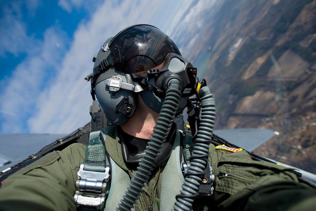

Things get a little more in depth when you get to pressurized aircraft.

These requirements are also listed in 91.211: 

1. If you’re flying above Flight Level 250, a 10 minute supply of oxygen is
required for each person onboard.

2. If you’re flying above Flight Level 350-410, and one pilot leaves their seat, the other pilot will be required to wear an oxygen mask, unless both seats are equipped with quick-donning oxygen masks.


There are three basic components to any oxygen system in an aircraft:  the storage system, the delivery system, and the mask or cannula. First, there are several types of storage systems. 

Gaseous aviators breathing oxygen is the first. This is the standard green tank that everyone is familiar with. There are two types of tanks. Either the high- pressure with 1800-2200 psi or the low pressure tank with 400-450 psi. The major issue with these and General Aviation aircraft is weight. Some of these tanks can get bulky and heavy and therefore don’t work for everyone. 

Liquid aviators breathing oxygen or LOX is another form of storage. The major advantage of LOX is that it has a 900 to 1 expansion ratio, meaning that 1 liter of liquid oxygen can be expanded into 900 gaseous liters of Aviators Breathing Oxygen. The disadvantages of LOX are they are extremely volatile and have to be stored at -197F. If it comes in contact with exposed skin, severe frost bite can occur. 

Sodium chlorate candles or oxygen generators have a weight advantage like LOX. They’re essentially a canister that when activated mix sodium chloride and iron powder and produce oxygen. They general have a 600 to 1 expansion ratio, which goes back to the weight savings. However, once these are started they are very hard to stop. Another disadvantage is these devices produce a fair amount of heat, so proper precautions need to be taken. 

Next are the delivery systems. The main systems are Continuous Flow, Diluter Demand, and Pressure Demand. Continuous Flow, is exactly as it sounds. The oxygen is allowed to flow continuously from the tank to the user. The benefits of continuous flow are you don’t need a complicated mask or regulator. The downside to this system is since it continuously pumps oxygen, you’re wasting oxygen when you exhale. Most of continuous flow systems are used on aircraft that generally fly below 28,000 feet. 

Diluter Demand was designed to fix the negative of the Continuous Flow systems. Diluter Demand only sends oxygen to the user when the user inhales. The system also allows cabin air to be introduced in, sending the perfect mixture of oxygen to the user when needed. These systems are very efficient and generally tend to be used up to 40,000 feet. 

Pressure Demand is designed to essentially “over inflate” the users lungs. This will basically pressurize the the users lugs and allow the user to fly above 40,000 feet. This is needed at flights above FL400 because 100% oxygen without positive pressure will not suffice. 

The final portion of the oxygen system is the mask or cannula. Nasal cannulas generally are more comfortable and are regulated to 18,000 feet service altitude. Masks come in a couple different variants. From re-breathers to quick-donning, most masks accomplish the same task with a few small differences. Quick-donning must be able to be put on within five seconds and are rated up to FL400. 

Since that was a lot of information, what does all of it mean to you? Most fair weather flyers will never run into any of this. However, the high performance owner/operator will run into oxygen use situations a fair amount. Taking the family up to Colorado on a ski trip, jumping up to 12,500 feet to get above some weather, or flying above 5,000 feet at night on a long xc are all situations where you may want to have oxygen on board. 

If you are planning on doing any of this type of flying or are currently doing these types of flights, training is a must. If you’ve never been in an altitude chamber, I would highly recommend it. In college, I went with a group to Oklahoma City to the FAA’s headquarters where they hold a class on Hypoxia and High Altitude flying. It’s very informative to be in the chamber as it simulates being oxygen deprived. You get to see how you’ll react and what kind of symptoms you’ll have when in a loss of oxygen situation. Each person has different symptoms, so it’s important to see how you will react.

It’s also good to fly with an experienced instructor. Finding an instructor who will allow you to learn in a safe environment is worth its weight in gold. 


Ryne Bergren is currently a First Officer with Mesa Airlines in the CRJ 900. Ryne has experience in many different areas of aviation, from corporate to airlines to teaching to ferrying across the Atlantic Ocean. His passion is for all things that travel across the big blue sky.

Similar Posts

  • The Aunt Betty Directive: PFD Failures

    Glass panel displays, ballistic parachute aircraft recovery systems, portable tablet computers enabling paperless cockpits, and widely available three axis autopilot systems have changed the way we fly, the way we train, and the way we are expected to perform on check rides. Our training and testing paradigms have tried to stay in synch, yet always seem to be catching up to the latest levels of technology.

    This is very apparent when we instructors are preparing a student for an FAA practical test. When training aircraft had no autopilots, no GPS, and certainly no parachutes, the general philosophy was that during training, the student should have the lowest level of technology available. This was also the expectation on the check ride. This theory has changed over the years and now the Practical Test Standards require that an applicant integrate all available technology while demonstrating mastery of his or her aircraft. This raises numerous questions from instructors and students about what technology will be available for each task.

    One example of this dilemma is found when contemplating an instrument airplane practical test in a Cirrus SR20/SR22. The test requires the task “Instrument Approach without Primary Flight Display”, which has taken the place of what was the partial panel approach, accomplished without use of gyroscopic heading and attitude indicators. In the Cirrus, the standby attitude indicator, standby airspeed, and standby altimeter are available, as is the Multi-Function Display. Guidance from the FAA has us shooting a GPS approach using the moving map display on the MFD after disabling the PFD. Those of us who trained and tested in steam gauge aircraft think that this task should be fairly easy. With a fully functional Attitude Indicator and a nice big moving map display showing our course, a reasonably competent instrument pilot should have little trouble adapting to this setup and flying a good approach.

    But, in the Cirrus specifically, and perhaps in other aircraft as well, another question comes up. Can the applicant use the autopilot (which still works just fine after a display failure) during the approach without the PFD? A rather famous DPE who writes for a national magazine says “yes”, opining that not to allow its use would be introducing simultaneous multiple systems failures, which is strictly forbidden in the minds of some. If we follow this logic, we would not test simulated engine failure emergencies in these aircraft either, because to do so would imply failure of not only the engine, but the CAPS parachute system as well. In my former role as a pilot examiner, I always said no, that the approach should be hand flown. Here is my logic.

    I was amazed that flight instructors and examiners would accept the substitution of autopilot technology for the skill required to fly an approach without the PFD. I would argue that the intent and the well described emphasis of the PTS is that the applicant must demonstrate the ability to control the airplane after a loss of the primary flight display, not observe and monitor the autopilot controlling the airplane! This argument was generally unpersuasive, so I approached from a different point of view, that of a concerned family member.

    “Aunt Betty” represents a future passenger flying with the soon to be rated instrument pilot. Here is the question posed to Aunt Betty: “When we train and test pilots for instrument proficiency, we require them to demonstrate the ability to safely and skillfully fly the airplane without their primary instruments. Now, Betty, in this airplane, we can test this task in one of two ways. We would like your input on which way you would prefer, seeing as you will be a frequent passenger with your nephew. We can either have the pilot (might be your son, brother, husband, or nephew) demonstrate that he can fly the airplane by hand without the PFD, which does require a little more skill and a slightly different technique, or, we can require the pilot to perform this task using the autopilot so that the pilot basically monitors the airplane flying itself on the approach.

    “Now, Aunt Betty, a pilot allowed to use the autopilot system on this approach may not have the skill or technique to fly the approach by hand in the clouds should the autopilot shut down due to turbulence or mechanical failure. Should this happen to a pilot without the skill and practice normally required, the odds of a fatal accident occurring would be quite high.

    “So what do you think, Aunt Betty? Would you feel more comfortable flying with this fellow if he has demonstrated mastery of the aircraft (sans PFD) without the autopilot or only with its assistance?”

    This leads us to a larger discussion about the use of other technology, iPad, GPS moving map, and more. If technology is used as a replacement for pilot proficiency during training and testing, we end up with less skillful, less competent and ultimately less safe pilots. But, if we require that our students demonstrate mastery with the lowest available level of automation and technology (which, by the way, implies excellent fundamental aircraft control skills) then, when technology is added into the equation, we have a safer pilot.

    Technology can be a value added safety multiplier, or it can be a crutch needed to make up for lack of fundamental and advanced skills. Crutch or Safety Multiplier, which one will you choose? I know which one Aunt Betty prefers.

    Charles McDougal is a flight instructor, corporate pilot, and former DPE ‎who offers basic and advanced flight instruction in the San Antonio area.  To find out more information about Charles or to contact him, visit his website, www.flighttrainingcoalition.com.

  • PIREP: Austin Bergstrom Recovering After Flood Damage

    The massive storms that rolled through the Austin Bergstrom and San Antonio areas last Friday not only put a dent in the landscape, they put a dent in the skies too.

    The Austin Bergstrom (KAUS) control tower suffered significant flood damage Friday.  6 inches of rainfall in an hour caused water to come pouring into the first floor of the tower, flooding the radar room and knocking out the power.  This led to transmission outages for the tower, ground control, clearance delivery and the ATIS.  Similar to the Chicago Center fire last year (though this was a much smaller section of airspace), the area normally controlled by Austin Approach was replaced by a big, gaping radar hole.

    By 8:45am on Friday morning, the Austin Bergstrom airport actually closed.  One runway eventually opened back up Friday afternoon, but massive delays and cancellations had already taken place.  All the ILS approaches were down and Houston Center had taken over the airspace normally occupied by Austin Approach control.

    Austin Temprorary Tower

    A temporary, emergency tower vehicle was brought in by the FAA (it’s essentially an RV with communications and a giant window) by the end of the weekend.  All arrivals and departures were restricted to 17L and 35R.

    Due to the radar outage, I heard there was as much as a 4 hour delay even for planes coming into Austin Bergstrom from Dallas, and that was in VMC conditions on Sunday and Monday.  Tuesday and Wednesday brought IMC conditions which only enhanced the delays.

    The latest news is that Austin Approach will be opening back up, but in a satellite base in San Antonio.  The Austin controllers will be using the SAT radar room and will be receiving their radar picture via satellite.  The approach frequencies should be up and running today or tomorrow.  The Austin Bergstrom tower is up and running and most of the ILS approaches are operational at this point.

    In the meantime, expect delays going in and out of Austin.  If you don’t have to get to AUS, EDC, or GTU, you’re better off delaying a day or two until Austin Approach is back up and running.

  • Dry Motoring a PT6

    When it comes to turboprop engines, a hot start is a really bad thing. For you piston drivers out there thinking, “What’s the big deal, you are just starting a hot engine,” then here’s a little education for you.

    In a PT6 turboprop engine, there is a very important temperature gauge that a pilot monitors very closely during each and every start. It is called the Inter-Turbine Temperature gauge, or ITT. This temperature is a measurement of the exhaust gases between the compressor turbine and the power turbine (s). In the picture below, the probe is located where the blue and red colors meet.

    In a turboprop engine, specifically the Pratt & Whitney PT-6 in all it’s different sizes and variations, there will always be a specific temperature that the pilot will want to keep the ITT below. This article will deal specifically with a Piper Meridian.

    A Piper Meridian starts hotter than almost any other PT6 engine because of the way it’s air intake is designed. Unlike other turboprops, the Meridian has a permanently open inertial separator. This means that not all the intake air makes it to the engine during start because some of it goes out the inertial separator opening. So, coming to a Meridian from operating other turboprop engines can lead to a little bit of a surprise on the ITT temperature being higher than what a pilot is used to when starting.

    As a rule of thumb, when starting a Meridian, never let a start continue when the ITT hits 875 degrees. Based on the chart below, you are still in the safe zone at 875 and have about a 50 degree buffer before you have to start getting worried.

    On cold starts with a good battery or a GPU, 875 is typically not an issue. Most starts when cold are going to be in the high 700s or low 800s. On a cold start, if you are seeing starts in the mid to upper 800s, try starting with a GPU and see if that lowers the start temperature. If it does, then that means your battery is weak and needs to be replaced. Another tell-tale sign of a weak batter is the Ng doesn’t spool up properly (meaning it settles around 12-13%) or takes a really long time to spool up. Also, never start on the battery with less than 24 volts.

    When there are multiple flights in one day, the pilot has to take into consideration the warm engine prior to starting. If the ITT, prior to the start sequence, is above 150 degrees, it is time to do some motoring of the engine.

    What is motoring? It is simply using the starter to turn the engine, which leads to air being sucked into the engine allowing the engine to cool off prior to start. The theory is, the cooler your engine prior to start, the cooler the ITT peaks at during start.

    Here’s the steps on how to dry motor a Piper Meridian:

    • Battery on
    • Strobes on
    • Fuel Pumps and Ignition off
    • Throttle idle
    • Condition Lever feather/cutoff
    • Push the start button
    • Monitor the ITT temperature
    • Reaching 150 degrees, if less than 30 seconds have elapsed:
      • Fuel Pumps on
      • Ignition On
      • Condition Lever run
    • Reaching 150 degrees, if 30 seconds have elapsed:
      • Push Manual/Stop button to stop the start
      • Let starter rest for 30 seconds

    The starter has a 30 second limit on the Meridian, followed by a 30 second rest period. You can do the sequence twice, then, after the 3rd start, there is a 30 minute rest period. Typically, if the ITT won’t cool down to 150 after the 3rd time, there is probably something wrong.

    The most important thing a pilot can remember is never, ever push the condition lever forward if the ITT is above 150 degrees. You’ll be well on your way to avoiding hot starts that way.

  • MODAERO NextGen Aviation Festival

    Looking for something different to do this Spring Break week?

    Modaero

    Consider checking out the First Annual MODAERO NextGen Aviation Festival in Conroe, TX.  It’s a fly in event, complete with camping opportunities, at the Lone Star Executive Airport, KCXO.  The festival itself is being held right next door to the airport at the Lone Star Convention Center.

    What’s the draw, do you ask?  Not only are there going to be representatives from all the major aircraft manufacturer’s (along with tons of airplanes), there will be a multitude of speakers and live music.  There are even drone races!  The live music sets the event apart from the well known national fly in events like Osh Kosh and Sun N Fun.  It’s a different type of Festival, geared toward the younger generation of pilots.

    For more information or to register, check out MODAERO’s website.  The festival runs from Wednesday through Saturday, March 16-19.

  • Cirrus Alternator Failure

    A Cirrus is an electric airplane.  There are no vacuum pumps and therefore no vacuum driven instruments. The Klapmeier brothers did this on purpose, trying to make it a modern airplane.  No vacuum systems means no vacuum pump failures, hence there is a lower likelihood of instrument failures in IMC.

    What Cirrus did instead was put a lot of electricity producing and storing devices in the airplane.  All SR20 and SR22s are equipped with 2 engine driven alternators and 2 backup batteries.  Alternator 1 is a 28 volt alternator (the amperage varies based on whether or not you have an air conditioner) while Alternator 2 is a 28.5 volt alternator.  There are 2 24 volt backup batteries, as well.  Battery 1 is also used for starting.

    In traditional airplanes that have 1 alternator, an alternator failure can affect a lot of things.  Depending on how many electronics are in the airplane, the battery can get depleted quite quickly.

    The Cirrus electrical system is quite ingenious.  It’s a little bit different based on whether you have an Avidyne Cirrus or a Garmin Perspective Cirrus.  I will discuss that further below.

    The main goal of this article is to talk through what happens in the event of a #1 Cirrus Alternator Failure (an Alternator 2 failure actually isn’t a big deal at all, though Alt 2 is required for IFR flight), the procedure for trying to fix it, and a technique I have developed that makes the pilot’s job easier.  First, let’s go through the #1 Cirrus Alternator Failure procedure.

    Alternator 1 Failure

    In either avionics configuration, the Cirrus Alternator Failure procedure is the same.

    • Check and reset the circuit breaker for Alternator 1 (Reset only once)
    • Cycle the Alternator 1 master switch
    • If Alternator 1 doesn’t come back online, leave the Alternator 1 master switch off and shed load on the battery

    Avidyne Entegra

    The Avidyne Entegra has 2 busses, the Main Bus and the Essential Bus.  Alternator 2 isn’t set to come on until the engine RPM reaches 1700.  While on the ground, Alternator 1 runs both the Main and Essential Buses.  In the air, Alternator 1 runs the Main Bus and Alternator 2 runs the Essential Bus.  Since Alt 2 is 28.5 volts, the higher voltage won’t allow the power from Alt 1 to cross over and run the Essential Bus.  There are also 2 one-way directional diodes that prevent the voltage from Alt 2 to cross over and run the Main Bus.

    Having said all that, when Alternator 1 fails, Battery 1 is now running the items on the Main Bus.  There are a significant number of items on the Main Bus which causes the 24 volt battery to quickly lose it’s charge. This precipitates the need for shedding load.  Items like GPS 2, the air conditioner and aircraft lights can all be turned off.

    In the above scenario, Alternator 2 is running the Essential Bus still that has all the Essential items on it.  Those include:

    • The PFD
    • Flight Instruments and associated Avidyne computers
    • Engine Instruments and associated Avidyne computers
    • GPS 1
    • Com 1
    • Nav 1
    • Autopilot
    • Stall Warning
    • Charging Battery 2

    Note 2 important items that are not on the Essential Bus:  the flaps and the landing light (which is very handy at night).  Those two are only on the Main Bus, which Battery 1 is now powering.

    Let’s further enhance our scenario.  You are flying over Nevada (quite remote and not a lot of airports) at night, 30 minutes from the nearest airport when your Alt 1 fails.  When you get to the airport you are planning on landing at, you want to have your flaps and your landing light, but we don’t know how long Battery 1 will last.

    The solution (this is where my technique comes in):  Turn off the Battery 1 master switch.  This is an easy solution to ensuring you have battery power to use your flaps and landing light.  Instead of going through and shedding load, simply turn off the source.  You’ll still have all the above items on the Essential Bus, which is all you need to keep safely flying.  Then, when you get to your landing airport, turn Battery 1 back on to utilize your flaps and landing light.

    Garmin Perspective

    Cirrus wired the Garmin Perspective plane a little bit differently.  There are now 2 Main Buses along with the Essential Bus.  Alternator 1 runs Main Bus 1, while Alternator 2 runs Main Bus 2 and the Essential Bus. Both Alternators are running all the time.  The Alternator 1 Failure procedure remains the same.

    The cool thing that comes along with the second Main Bus in the Perspective is the amount of items you still have available to you in the event of an Alternator 1 failure.  The only items you lose will be:

    • Yaw Damper
    • Landing Light
    • Air Conditioner and associated components
    • EVS Camera
    • 12 Volt power supply in armrest

    Everything else is powered off of Alternator 2.  That’s not much.  The only item you really want on the above list is the landing light if you are going to be landing at night.

    Follow the Alternator 1 Failure procedure, then do my technique again.  Turn off Battery 1 to save the battery power in order to use the landing light when needed.

    Cirrus did a great job creating an all electric airplane with plenty of backups in case something fails.  I focused mainly on the Alternator 1 failure here.  If Alternator 2 fails, the system is wired for Alternator 1 to run everything while still charging Battery 1 and 2.  No big deal.

    In my experience, turning off Battery 1 to conserve battery power is just a simpler solution when shedding load in the event of a Cirrus Alternator Failure.

  • Determining Pattern Altitude

    Figuring out the pattern altitude at an airport should be pretty simple, right?  But, in this day of helpful technology, most pilots actually get it wrong.  How can you always get it right?  Well, it just takes about an extra 15 seconds.  Here’s how.

    Traffic Pattern
    John Wayne Airport Traffic Patterns

    As outlined in the Aeronautical Information Manual, section 4-3-3, “traffic pattern altitudes for propeller-driven aircraft generally extend from 600 feet to as high as 1,500 feet above the ground.”  Further, in the Pilot’s Handbook of Aeronautical Knowledge on page 13-10, it states:  “1,000 AGL is recommended pattern altitude unless established otherwise.”

    Okay, so for piston driver’s, we’ve got it narrowed down to 1,000 AGL (Above Ground Level for those who don’t like acronyms).  But wait!  There’s that very important phrase at the end of the last quote:  “unless established otherwise.”  That means not all airports have traffic pattern altitudes of 1,000 AGL, or else they wouldn’t put that line in there!

    How do you find out what the TPA (Traffic Pattern Altitude) is for a certain airport if it’s not 1,000 AGL?  Great question!  Your first guess is probably to look on Foreflight.  Though this is a good start, it is not the full answer.

    Let’s use an example.  Look up KAQO, the Llano Airport on Foreflight.  At the top of the page, the airport elevation is stated as 1,101′ MSL and the pattern altitude is stated as 1,902′ MSL.  From what we just learned, 1,902′ MSL is not 1,000 AGL, so is 1,902′ MSL otherwise established?

    On the Airports page with KAQO pulled up, tap the A/FD tab, second to last on the left.  Scroll down to Llano Muni.  Read the whole entry.  Does it state in the entry that pattern altitude is different than 1,000 AGL?  It sure doesn’t.  So, because it is not otherwise established, pattern altitude at KAQO is 2,102′ MSL not 1,902′ MSL.

    Where did Foreflight get that?  I have no idea.  Too often, though, pilots look at the Foreflight pattern altitude and don’t actually check the Airport Facilities Directory (A/FD).  Then, they get the pattern altitude wrong.

    What does it look like when pattern altitude is otherwise established?  Look up KSGR, Sugar Land Regional, on your Foreflight app.  Foreflight states the elevation as 82′ MSL and the Pattern Altitude as 1,000′ MSL.  Is this correct?  Well, tap that A/FD button again and let’s find out.

    On the second line of the A/FD entry, it says TPA-See Remarks.  Down in the remarks section, we find the following:

    TPA-1000 (918) single engine piston acft, TPA-1500 (1418) for twin and turbojet acft, TPA-500 (418) for helicopters within 2NM.

    Foreflight got it right this time for single engine pistons, but if you are in a twin, the pattern altitude is different.  What’s the lesson here?  Always check the A/FD and don’t always go by what Foreflight says.  The A/FD is always right and usually has a little more detail to help set you straight.

    One last thing.  Both the AIM and the Pilot’s Handbook of Aeronautical Knowledge, when talking about pattern altitude, state, “When operating at an airport, traffic pattern altitudes should be maintained unless otherwise required by the applicable distance from cloud criteria in…section 91.155.”  91.155 defines basic VFR weather minimums.  So, to fully interpret what the AIM is saying, we have to take into account the type of airspace we are in to determine if we can safely and legally operate at pattern altitude at a particular airport.

    For example, let’s say we are at KCVB, the Castroville Airport.  Pattern altitude there is 1,602 feet, which is 829 AGL.  CVB is Class G airspace up to 700 AGL, then Class E above that.  Let’s say there is a 700 AGL broken cloud layer.  Pattern altitude is 829 AGL, so you won’t be able to get up that high with a broken ceiling.  What altitude can you do pattern work at to stay legal?

    Class G VFR weather minimums during the day below 1,200 AGL is 1 SM visibility and clear of clouds.  So, legally, you could fly at 699 AGL (which at CVB would be 1,472 MSL) while in the pattern and be legal.  Safe?  Maybe, but probably not if you are skimming the base of the clouds.  Is 1300 MSL a safer pattern altitude in this example?  Well, that is 527 AGL, so probably not, since towers tend to stick up that high sometimes.

    Let’s go back to KSGR and put a 1,000 AGL overcast ceiling there.  SGR is Class D airspace and we already determined pattern altitude there was 1,000 MSL for piston singles.  VFR visibility and cloud clearance requirements in Class D airspace are 1,000 feet above clouds, 500 feet below clouds, and 2,000 feet horizontally from the clouds with 3 SM visibility.  In order to stay 500 feet below the clouds, you would be flying a 582 MSL pattern.  Safe?  Probably not, though it is legal.

    To summarize, don’t take Foreflight’s word for pattern altitude.  Cross reference the A/FD (it only takes 15 seconds at the most) to verify.  If it’s cloudy, it’s really best to stay on the ground, but if you want to find out your legal pattern altitude with a cloud deck, cross reference 91.155.  I don’t recommend flying below pattern altitude because it is there for a reason.

Leave a Reply

Your email address will not be published. Required fields are marked *